“E-Goalie”
Contents
Introduction
Initial Design Phase
2nd Design Phase Design #1: 4 Steppers Goalie
Vision
Software
Hardware
Hardware & Actuation
Initial design
Software: controlling the motors with LabVIEW
Hardware: choosing the right motors
Experiments & Data Analysis of Stepper Motors and Vision
Getting The Stepper Motors to Work
LabVIEW Stepper Motor Testing
LabVIEW Code Testing
Final Design Phase - Design #2: Servo
Final Design
Testing/calibration
Conclusion
User Test (extra)
Introduction
With 3.5 billion fans all around the world, soccer is the most popular sport in the planet. Revenue associated with soccer in 2013 alone approached a figure of $35 billion. In comparison, all the sports in the US combined–American football, baseball, hockey, basketball, stock-car racing, and college sports –accounted for a bit over $25 billion during the same period of time. But soccer, like any team sport, is no fun playing alone.
As part of the Microprocessor-Based Mechanical Design course ME235, students were challenged with building a mechanical project utilizing NI myRIO and LabVIEW. Requirements for the project were, among many things, a design that was Real Time and utilized Multitasking capabilities. With a blank canvas ahead, a team of 5 Product Design Engineers and one Bioengineer got together to take on the challenge of the course. And this is how Team Radicle began its journey, with 3 goals in mind:
Create something useful for society
Create something fun
Allow for every member of the team to grow in areas of personal interest, keeping in mind motivations and skills.
The team quickly came together to designate and solidify meeting times. Based on everyone’s schedule, we cemented 2 solid days a week to meet, keeping in mind the remaining availability for cases that necessitated stronger team interaction. Subteams were created to handle research and testing of Vision and Motors independently. During the second half of the semester the team would get to see each other more and more as the project progressed. Right from the get go, Radicle members began delineating a focused pathway to conceptualizing a design. The first week’s assignment was meant to bring individual ideas as to a prototype. We drew from personal interests and found that commonalities lied in sports and social impact. We developed design concepts and finally narrowed down our choices into one, E-Goalie. Soon after, we built a schedule to follow with milestones to reach, and we set on our way towards achieving our goals.
E- Goalie, the design we chose to pursue, a ball-tracking, automated Soccer Goalie, is a device that allows the user to improve soccer skills. It is intended to improve shooting performance of a soccer player by blocking the majority of shots and allowing target practice. Although some robotic goalies have been designed in the past, none had been intended for personal consumer use, let alone designed to be lightweight and carried by the user. Moreover, the team found no other project on the web similar to this one, making our design unique. Our team’s original intent, was to create a device that the user could carry in a backpack, take it to a soccer field and easily attach it to the goal post. We wanted to build a device that would create an immense user experience, one that could have the potential for commercialization and especially contain important positive societal impact. Building confidence and competency in kids was our societal goal.
Throughout this paper, we will present the many ways we went about pursuing the implementation of the E-goalie design and the many pivots we were forced to make due to monetary, experience and ultimately time constraints. We examine the research undertaken that informed our design, the challenges we believed we would encounter and the choices made as a team to moved the project forward through unforeseen obstacles. Finally, we culminate the project with a user test as kids utilized E-goalie in a real life scenario.
II. Initial Design Phase (Conceptualizing)
First, we had to choose a design for our soccer goalie as there are many ways to implement this idea. We explored the landscape of existing projects involving autonomous goalies and players for different sports (soccer, table-tennis, hockey…) as well as rope technologies to find inspiration and start building our understanding of the field. I will present below the three main sources of inspiration we built up on.
Robot Kaleci: the robot soccer goalie that defeated Lionel Messi
Robot Kaleci is a robot goalkeeper famous for defeating Lionel Messi, one of the all time greats soccer player, during a penalty session. The system uses two camera that tracks the position of the ball in real-time at a speed of 90 frames per second. Image processing is then used to guess the possible points where the ball will cross the goal line. Finally, the information is transmitted to the actuators and motors in order to move the goalie in the direction of the incoming shot. As you can see on figure 3., the robot is fixed to a support in the middle of the goal. It can pivot by 90 degrees right or left, with respect to one axis of rotation perpendicular to the plane of the goal, allowing it to cover the entire goal surface area.
Ulf Hoffmann Tischtennis Roboter (UHTTR-1): the Ping Pong Master
We found our second source of inspiration in UHTTR-1, the Ping Pong Master. UHTTR-1 is an articulated arm that plays the role of a tennis table opponent. It moves along a rail located on the baseline of the ping-pong table and is articulated to hit the ball.
3. SpiderCam and Skycam: examples of rope technology
The Spidercam is a computer-controlled, cable-suspended camera system which enables film and television cameras to move over a specific area, for example a soccer field or a tennis court. The system has four motorized winches positioned at each corner of the covered area and Kevlar cables going from each winch to the camera. By controlling the winding and unwinding of the cables, the system allows the camera to reach any position of the three-dimensional space.
From our research, it became clear that we would need to combine computer vision software and actuation software to meet our challenge, which would fulfill the requirement for multi-tasking. In addition, it would require a real-time image processing and actuation to be able to stop the ball in time.
Drawing inspiration from these projects, we came up with three main design concepts for our soccer goalie.
Our first concept was a goalie that would move horizontally on a rail. The goalie would be made of two parts: a rigid bottom part attached to the rail and a top part that would have two arms able to rotate in respect to the center of the goalie.
Design concept 1 - Linear slide + articulated arms
The second one was a robot fixed in the middle of the goal that would rotate in respect with one rotation axis, similarly to Robot Kaleci.
Design concept 2 - Pivoting goalie
The third concept - the one we were most excited about - was a “glove” attached to the four corners of the goal with ropes. The “glove” would be controlled by the winding and unwinding of the cables and would be able to move in two dimensions, therefore covering the entire surface of the goal.
Design concept 3 - Cable suspended “glove” with four motors
In order to substantiate the feasibility of our designs and take an informed decision, the team split into two-subteams, one researching hardware while the other focused on software. In the end, we chose to pursue the last option as it was the one we were most excited about as a group. In practice, this choice was also motivated by the three following reasons:
The design would allow us to cover the entire goal
We could set up two user modes: “target practice” and “beat the goalie”, which would enhance the user experience. In “target practice” mode, it would be possible to set the “glove” at a certain position in the goal so that the player practices its precision by trying to shoot at it. In “beat the goalie” mode, the goalie would try to stop the shot.
It would require to run multiple motors running synchronously, which was an engineering challenge we wanted to take on.
We anticipated challenges both in terms of hardware and software. First, computer vision would play a critical role in our design. However, nobody in the team had previous experience with it. Additionally, we knew that running the four motors synchronously would be a difficulty. Finally, there was a mechanical challenge linked to the power of the motors as the glove has to move fast enough when it gets the information about the position it needs to travel to.
III. Second Design Phase: Making it happen
Design - 1: 4 Steppers Goalie
Having arrived to our concept of a goalie suspended by four cables and actuated by four motors, we began to divide tasks to improve productivity and avoid time delays. In order to do so ,the team of 6 split into subteams once again , this time into teams that would explore and develop the vision side of the project and that would develop the motors (actuation) side of the project independently, before implementing integration.
Vision
Software
The goal of the vision team was to detect the soccer ball and then output the 2D coordinates to send to the motor team for actuation. We took a step-by-step approach, first trying to detect black dots on a white background in a series of static images, then moving to video, then replacing the dot with a colored ball, and varying the distance of the ball from the screen.
We attempted to build the code from “scratch”, using the IMAQdx building block functions. Unfortunately, the examples and LabVIEW documentation for relevant applications were sparse and only tangentially relevant, so while finding a black dot in an image was fairly straightforward, moving to a video file was difficult. We decided not to reinvent the wheel, but to test the Object Tracking Express Function in the Vision Assistant. This involved experimenting with the object tracking parameters in the Vision Assistant in LabVIEW. Adjusting the number of histogram bins (for degree of importance of color) and tracking score provided progressively better object-following. However, for our application it was imperative to follow the object as the ball approaches the goal, which involves a dramatic change in size of the ball. Object Tracking fortunately has a shape-adaptive mean shift option, which allows adaptation for rotation, shape change, and most importantly, scale change. The problem with this approach was that any time we tried to use the shape-adaptive mean-shift, the system crashed.
We consequently transitioned to Color Pattern Matching, which allowed us to track an object based on the pattern of colors in a ROI (region of interest) in a reference image. After testing with various colored objects in different lighting and varying relevant parameters, we were able to track the ball in its movement toward the goal. To help visualize, we overlaid a rectangle to tell us to the position of the ball, and output the coordinate of the center of the ball relative to the camera view.
We considered various models for projecting the coordinates of the ball as it crossed the plane of the goalie. We planned how we might use a second camera to track the depth, or base it on ball size in each frame, or map out a parabolic path based on its initial trajectory. We decided to focus on first getting the actuation system setup. If system was fast enough, we could simply move the goalie to the current detected location of the ball.
Hardware
The core hardware of the vision system is the camera; it was imperative to select a camera which would satisfy the requirements of the project. We started by listing out few features that were desired for the camera, such as:
High frame rate (frames per second)
Wide view angle
High resolution
Compatible with myRIO
A video output from a camera is a continuous processing of images at a certain rate, commonly known as frame rate or frames per second (fps). A high frame rate camera allows to take more pictures per second and in process improves the quality of video. A better quality video would in turn increase the ease of spotting the ball for the software. Also, a higher frame rate means that software would analyze more number of pictures every second and this ensures that the software won’t lose track of a fast moving football. But cameras above 30 fps are very expensive, so we decided to use a camera rated at 30 fps.
Another feature of the camera that was critical for the vision system was resolution. A high resolution video output is generally bulky and very large in size. Although image processing was done on the computer, a very high resolution video would have increased the processing time. In addition to this, since we were using color pattern matching for ball tracking, a high resolution video gives exceptionally high number of true colors which software cannot differentiate very easily. Moreover, the color of an object changes slightly with change in ambient lighting due to which tracking of an object based on color becomes difficult with high resolution video since they are color sensitive.
All the aforementioned factors helped us in making an informed decision about which camera would be suitable for this project. After a lot of research, we decided to use Creative’s LiveCam series webcam model VF0790. The specifications of the camera are as follows:
Video playback at 30 fps
Video capture at 720p HD quality
Video/Image resolutions up to 1280 X 720
Still image capture 5.7 MP
But one of the biggest factor that influenced selection of this webcam was its compatibility to run with LabVIEW.
Link for the camera:
Hardware & Actuation
Initial design
The Hardware for E-goalie was initially composed of four motors, a goal, wires or strings and the goalie (or glove). The hardware team (motors) set a timeline to successfully accomplish the hardware milestones in time for vision code integration and leaving some headroom for testing and improving the design.
At first, it was essential to decide the size of the goal and of our goalie thereafter called “glove”- as the choice of the motors completely relied on it. After researching typical sizes of small goals and balls, we settled on the following: we would purchase a goal of 48 inches wide by 30 inches high and would build a “glove” of 9 inches square.
Initially, we were ambitious and wanted a glove that could resist balls coming at a high speed (45 mph). Therefore, we needed a resistant material. We went to the machine shop and asked for advice. We were told that polycarbonate would perfectly fit our purpose. However, for financial reasons, we decided not to pursue this option. As a cheaper alternative, the lab manager advised us to use Oriented Strand Board and this is what we chose. Now that we had the dimensions of our goal and glove, we were ready to determine the equations that would power we would need out of our motors.
Software: controlling the motors with LabVIEW
The team designed the glove to continuously follow the ball as it approached the goal. Therefore we wanted our glove to reach the position of the ball that the vision system had located in the (x,y) plane of the goal. So, one of the input to the motor control code would be the (X,Y) coordinates of the ball. Based on those input we needed to calculate the final length La, Lb, Lc, Ld shown in the figure below. Initially we thought about connecting the wires to the four corners of the glove. However, we realized that this design decision would generate very complicated calculations for the four lengths. Each length would be dependant on an angle theta (shown in the figure below on the right) which relates to the position (X,Y). Solving for theta also varies from one corner of the goal to another.
To avoid unnecessary complications, we decided to change the design so that the angle theta is constant and equal to zero at all time. To do that we decided that our design would connect all the wires to the center of the glove. However, the challenges we were facing now is the stability of the glove. To reduce torque requirements we chose to replace the wooden glove with a net. If the wires were connected to the center of the net, the net would fall under its own weight. To overcome this challenge, we added a cross polymer tube to which the net will be mounted on as shown in the figure below.
The wires would be connected to a hook that is drilled into the cross bar as visualized in the figure below.
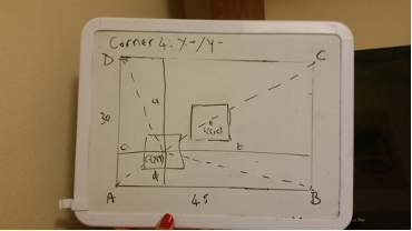
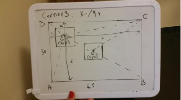
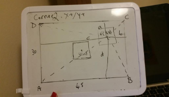
Having settled on the design. We now moved forward to calculate the lengths La, Lb, Lc, Ld. Based on the input (X,Y), we created a sub-vi called abcd. abcd will calculate 4 length a,b,c and d illustrated in the figure below. The figure shows a scenario where the (X,Y) position identified from the vision system lies in the 4th quadrant. In this case X is positive and Y is negative.
a = (goal height/2) - Y
b= (goal width/2) - X
c= goal width - b
d= goal height - a
In our case, our goalie height was 30 inches and width was 48 inches.
These equations are the same even if the glove was in the other 3 quadrants as shown in the figure above.
These distances are important to calculate the final wire lengths from the 4 corners. The LabVIEW program for “abcd” is shown below.
“abcd” (captioned in the block diagram of the “main vi without vision subvi” below as “Motor A”, “Motor B”, “Motor C”, and “Motor D”) will output these distances which will then be inputs for the second sub-vi called “getting the travel distance” (captioned in the block diagram below as “distance dA”, “distance dB”, “distance dC”, and “distance dD”).
The LabVIEW program for “getting the travel distance” is shown below for the particular case of the travel distance dA.
This SubVI calculates the final wire lengths from each corner. Depending on the input, the SubVI (in this case the inputs were c and d) outputs the length associated with a specific motor (in this case motor A)
La= (c^2+d^2)^0.5
The travel distance delta_d is equal to the difference between the original length La0 and the final length La.
delta_d = La - La0
This distance delta_d can be either positive or negative depending on the location of the glove and on the motors. In order to reach a particular position (X,Y), some motors will need to turn to extend the length of the wire in the goal frame while other motors will need to turn in reverse to pull the glove towards them and therefore decrease the length of the wire in the goal frame. For example, in the figure below delta_d for motor C and B will most likely be negative while delta_d for motor A and D will be positive.
Having calculated the travel distance delta_d for each motor, we now need to calculate the speed at which the each motor will turn as well as the direction (clockwise/counterclockwise) that the motor will turn and output that to the motor control vo. This was done in the SubVI called “PPS_time_direction”. As shown in the block diagram of “main vi without vision subvi”, PPs_time_direction” takes as input the output delta_d of “getting the travel distance”. The block diagram for “PPS_time_direction” is shown below.
This SubVI checks if the distance detla_d is positive. It it is, it output a boolean of value “True”. It also calculates the Pulses Per Second which will allow us to control the speed of the motor. The Pulses Per Second is calculated based on the equation below:
PPs= (deltad / 2PiRs) * SPR /deltat
Where Rs is the radius of the spool in inches
SPR is the number of steps per revolution for the motor
detla_t is the time constraint that we impose on our system and is the maximum travel time allowable to travel the distance delta_d
“PPS_time_direction” should output the PPS, time constraint detla_t and the direction (in boolean value) to the motor control vi.
Hardware: choosing the right motors.
Choosing the motors was by far one of the most complex parts of the entire process. It required time and most importantly, expertise that all members lacked. Stepper motors were initially chosen by the team as the go-to motor after an assessment period for their ability to “count step”. They were chosen above DC for the ability to be controlled more precisely with lesser effort and at a lower cost. Little did we know at the time that this assessment was lacking important information on stepper motor ratings and speed considerations. At this phase of the process, soon after returning from spring break, we decided it was best to seek answers from experts. We initially contacted Tom, a great resource that guided us immensely with getting to know motors. After failed attempts of going at it alone, we called Pololu, as well as various controls students and even tapped into professor Liu’s expertise for help into acquiring the correct stepper motor, one that could allow for our goalie to travel over 2 feet in 0.1 seconds. It was a fast condition. The answer however, always turned out to be something like this…”This is a difficult problem you got in hand” and “There is no easy solution for this, we can’t point you to the correct motor”. Even when asked to point us towards their fastest stepper motor selection, Pololu was reluctant to point towards a possible answer by replying “We don’t know what fast means to you”. Professor Liu was kind enough to offer suggestion into the math associated with calculating the requirements but even then we had trouble finding appropriate motors at a price point sensitive to our needs. Through the process, we learned that steppers are not rated by power but by their speed and torque curve, often necessitating the ability to understand and read PPS (pulses per second) and how they relate to the overall speed and torque.
We initially worked with one stepper motor Pololu #1208 and an A4988 motor driver that would control it. After learning its top speed, the team began debating weather to scale down the actual design or continue with bigger motors. A second slightly bigger motor was bought, Pololu#1206, before understanding in depth the properties of a stepper and the torque vs speed curve, as well as the Voltage and Current requirements. Once again, the lack of expertise had us unaware that a higher NEMA rating (bigger size motor) does not necessarily equate to a higher speed. The importance of matching up the correct voltage and current was an important key aspect that we had undermined up until this point and failed to account for the 1206’s need for a lower voltage motor control. The result were time delays as we tried to test and procure the correct motors. Circuitry issues were also abound. A few boards burned in the process as well as a few motors. We began to be more careful with the voltage supplied and learned to appropriately tune the motor control boards to the correct amperage as that of the motors being fed.
We finally decided that we would consider a smaller version of the goal entire design to utilize lower speeds and ordered what we mathematically equated as fast. Unlike expectations, these motors turned out to be only slightly faster than the previous two. Parallel work at this point began on exploring DC and Stepper motors.
Experiments & Data Analysis of Stepper Motors and Vision
Getting stepper motors to work
All motors went through a similar steps when the team began getting acquainted with them. We began this procedure with the stepper motor. Since, we were all new to myRIO and the motors, we decided to begin testing on an Arduino Uno first. Because we were all comfortable with Arduino’s language we took on the following approach:
Test on Arduino
Get Motor to Run
Get Motor to Run Fast
Control Motors Direction
Control Motors Direction and Speed together in the code
Test on myRIO
Transfer Circuitry into myRIO
Interpret Arduino’s Code Logic in LabVIEW
Repeat Steps 1.1-1.4
Integrate E-Goalie code
Software
Test E-Goalie
By following this approach, the team believed we would minimize error and optimize our time since the we felt that this approach erased the possibility of having one part of the system fail and not know where the failure lied (e.g. software or hardware, myRIO or motors).
LabVIEW stepper motor testing
Following successful trial and testing of stepper motors using Arduino, team moved into next phase, testing on myRIO. Stepper motors are generally picked up for projects where easy and accurate motor control is desired. We started by developing a simple code for testing Pololu’s #1208 controlled by A4498 motor driver. This testing allowed for controlling the speed and direction of the motor using LabVIEW front panel. In process of testing, we realized that Stepper motors that we tested were not fast enough but can be controlled easily.
LabVIEW code testing
To test the success of the code, we decided to calculate by hand for an example case. Taking X= -12 and Y = 8
a = (goal height/2) - Y
b= (goal width/2) - X
c= goal width - b
d= goal height - a
a= 15-8 = 7
b= 24 - (-12) = 36
c= 48-36= 12
d= 30 - 7= 23
La= ((c^2) +(d^2))^0.5 = 25.94
Lb= ((d^2) +(b^2))^0.5 = 42.72
Lc= ((a^2) +(b^2))^0.5 = 36.67
Ld= ((c^2) +(a^2))^0.5 = 13.89
delta_dA= 25.94 - 28.3 = -2.36
delta_dB= 42.72 - 28.3 = 14.42
delta_dC= 36.67 - 28.3 = 8.37
delta_dD= 13.89 - 28.3 = -14.41
PPS_A = -2.36*200 / (2*3.14*1.5)*(0.5) = -100.2
PPS_B = 14.42*200 / (2*3.14*1.5)*(0.5) = 611.5
PPS_C = 8.37*200 / (2*3.14*1.5)*(0.5) =355.4
PPS_D = -14.41*200 / (2*3.14*1.5)*(0.5) = -600.42
These values are in accordance with the values that the LabView Program outputs.
Analysis (failure to perform as originally intended)
Due to the apparent lack of experience in this particular subject, the team spent countless hours reviewing content online relating to stepper motors. Our procurement of the correct motors proved to be a challenge from an economical perspective – the team spent over $300 dollars by demo day. There were not many relevant examples of steppers being used in projects on videos offered by NI as well as individual projects posted online. We finally made the decision to move to a different kind of motor. This however, robbed us of precious time since we were particularly headstrong into making the steppers work and did not pivot fast enough. We were married to the design and were slow to adapt.
IV. Final Design Phase - Design #2: Servo
Final Design
As we had mentioned previously, our original idea was to consider stepper motors due to their precision and control which does not require feedback. However, after conducting tests and experiments, we realized that the stepper motors we had were not fast enough for our application and required additional torque to move the wooden glove. Therefore we were faced with two technical challenges to overcome: speed and power requirements. With regards to power, we decided to adjust our design to minimize the torque needed by replacing the wooden glove with a lighter material such as a net. However, speed was still an issue.
We decided then to try servo motors which provided precision as well as better speed performance. The downside, however, was that they do not perform full revolutions. To overcome that, we thought about using spools of large radiuses which would allow us to achieve the wire extension/retraction with the small rotational angle of the servo. Yet, seeing the dimensions of the goalie we had, the spools would be unreasonably large. Therefore we decided to no longer adopt the 4 motor goalie design and move forward with a single motor design. The single motor design sought to effectively make use of the servo motor’s nature by putting the limited rotation performance at the center of the design. The servo will now be attached to our goalie. The rotation of the servo and therefore the goalie, intuitively reminds the user of an actual block attempt. This decision brought its own challenges however. The goalie needs to be of the same height as the goal and even a bit longer to be able to block goals in the top corners. Seeing the dimension of our goal, the goalie would have to be very large which would create a large torque requirement for the servo. Here again we had two options, the first was to get a bigger and more expensive servo. We considered that option but were faced again with financial barriers. Moreover, we realized that even if we had bought a higher torque servo, the motor options we were looking at all had lower speed performance. The second option was to scale down our design, which would scale down our goalie, require less torque, and was cost-effective. That is how we reached our final design for our goalie.
Testing/calibration
In order to create a final product, integration of both the vision and actuation components of the goalie project was necessary, Three main components were necessary for integration to be successful: the x,y coordinate obtained from the vision component needed to be given to the myRIO. The myRIO needed to translate the x,y coordinate to an angle and the angle needed to correspond to the correct duty cycle and frequency in order to move the servo to the correct position.
Using a dedicated servo control VI(Fig 29), we were able to figure out relatively precise control of our servo motor. Initial calibration of the servo motor showed that an angle between 0 and 90 could be converted to pulse width in ms by dividing by 100 and adding 1.5. Because the servo required negative numbers in order to turn counter clockwise, our initial solution only allowed the servo to turn a quarter circle instead of the half circle that we needed. Instead, the angle was scaled to a range between -180 and 180 and converted to pulse width by dividing by 200 and adding 1.5. Converting to duty cycle could then be easily accomplished by dividing the pulse width by 100 and multiplying it by a frequency, which in essence dictated speed. This led to a final formula of:
Duty cycle = ((Angle/200)+1.5)/1000 * Frequency
Translating the horizontal and vertical position to an angle necessary for the myRIO also had unexpected challenges. Initially we assumed that angle could be calculated directly from
tan(theta) = height/horizontal position
During testing, however, we discovered that because we needed a negative angle in order to convert to a pulse width, height and horizontal position were inverted. In other words, instead of thinking of the goalie as a horizontal position (Figure 18A), it was necessary to think of it in a vertical position (Figure 18b)
From these calculations, it was possible to convert angle to servo position using the following VI
During testing of the integrated project, issues still remained to be solved. Because the vision program was unable to continuously track the object, often losing the object momentarily, a default pos (x,y) position of 0,0 would be given to the servo causing it to jerk wildly between the tracked and default position. A case structure was therefore created to discard any 0,0 values which immediately increased performance of the goalie. In addition, because color pattern was tracked vs the actual object itself, the tracked object’s position often jumped around significantly. In order to remedy this problem, a smoothing component was added to the program. Instead of giving every single x,y coordinate to the servo, the software would instead collate a certain number of tracked frames, average the output sending the final result to the myRIO. The smoothing factor, or number of frames that were captured to average could be controlled by the user. While adding this component to the program improved the performance slightly, we also found that adjusting the smoothing factor could be used to adjust the difficulty level of scoring goals. Increasing the smoothing factor, while making the goalie move in a more fluid fashion, also decreased the speed. All these factors were incorporated into the final VI.
As can be seen, several additional performance and visual enhancements were added to the software. In order to demonstrate that the object was truly being tracked, a bounding box was created. In addition, in order to increase performance, an added option to remove visual feedback was also added.
V. Conclusion
We believe that this project was most insightful for all team members. We learned a lot and faced various challenges. Not only was this design unique in the sense that a system comparable to this (4 motors in each corner) has never been implemented in an automated goalie before. But it also represented an opportunity for all of us to get out of our comfort zone and try to design something not found in an instructables page online. As we look back and reflect on the past semester, here are some lessons we took from our experience.
First, we now agree we had our priorities misplaced when it came to our design requirements. We wanted our goalie to have good precision in order to effectively block the ball which made us focus on steppers and servo motors. However, we later realized that given the size of the ball and the goalie, precision should not have been the main priority. In all our designs we were facing technical challenges related to speed performance and not precision. That should have been a signal for us to venture into brushless DC motors, which although are more complex to control and do not offer the level of precision that servos and stepper would, they are usually much faster. Therefore, the lesson learned here is to more carefully identify performance objectives in the early stages of the project (e.g. should we go for precision or speed).
The other lesson we learned was that diversity in a team is important in the work environment. Our team was composed of 5 product design engineers and one bioengineer. Although the team was good at breaking down and assigning work, It is possible that having a controls engineer on board might have kept us from spending time and money on testing out different means to make the equipment work as well as to provide better insight into DC control. However, although our team members had no hands-on experience with motors, motor control, or LabVIEW before this course, we also strongly feel that the lack of technical diversity was actually a positive thing in the context of a university course project. The roadblocks compelled us all to unite forces which developed our communication and teamwork skills and pushed us to learn new things. If our team was made of members each specialized in their own field, each member would be working on something he/she already knew and that would not have given us the opportunity to learn and explore new fields. In fact, we have all gathered more knowledge now about motors, LabVIEW programming, and computer vision which is extremely relevant for our career.
The third lesson we learned was that early stage prototyping is crucial. We went with a waterfall approach where we had consecutive milestones to reach. We thought that we should focus a lot on researching potential solutions, learning more about motors, calculating the power we might need, etc. to reach theoretically the best optimal product. We realized however that we learned best when we tried to prototype, failed, brainstormed solutions, and tried again. Therefore, we now feel that the best approach would have been to prototype a minimal viable product in the early stages to identify challenges that we would face early on in the process, overcome the challenges, and iterate until we reached the most optimal product. In short, the final spaceship that makes it to the moon shouldn’t be the first spaceship we build.
The final lesson we learned was that we should not have become “married to one design”. We focused most of our effort and time to try to make the 4 stepper motor design work. Yet, what we should have done was iterated more often, create subteams within the subteams to seek out lo-fi prototypes of distinct designs. Then we should have experimented with these various designs in the early stages instead of learning how to make one large design work. By following this method we would have evaluated each concept’s pros and cons, and followed through with the winning concept.
Overall, we believe this project was an amazing, challenging opportunity to grow as an engineer. Our team agrees that while having an time machine to go back in time would certainly change the way we approached the project, we appreciate the lessons learned in the incorrect approaches we did take. Would we change things if we had the opportunity to go back in time? Sure, but the strength of the lessons learned lie not in the past but rather in the future, where we now have the confidence and the know-how to tackle similar problems.
VI. User Test
A group of kids from OIS middle school attended our demo presentation. Although the project did not come out to our mechanical expectations, the kids seem to be intrigued by it and enjoy playing with it. They did not care that the ball was not being stopped all the time by the goalie. Kids did however, notice that the goalie would fail to follow the ball at times and would take advantage of this by kicking it faster and to areas where the goalie would not reach in time. They began kicking the small ball from afar, and got closer and closer to the E-goalie as time went on, making the system more error prone. At one point a kid grabbed the ball and began moving it in front of the camera, trying to figure out how the system worked. The kids, all had a great time. So much so that their teacher sent me a personal email thanking the group for our demonstration and to send us pictures and videos of proof that the kids had fun. Observations, demonstrate that integrating such a mechanical device with a sport like activity that kids recognize makes them more willing to participate. Although our initial intent of providing a skill improvement method is not necessarily explored in this user test, it does show the ability to attract a child’s attention while integrating a competitive component via the E-Goalie